NaniteAFM

NaniteAFM Integration
Distributor & Service Provider In India
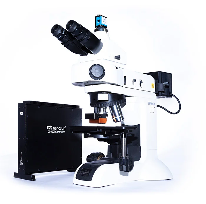
Inkarp Instruments, a trusted Nanosurf partner, offers NaniteAFM Integration in India, revolutionizing Atomic Force Microscopy (AFM) by seamlessly integrating with optical microscopes.
The smallest AFM for custom integration
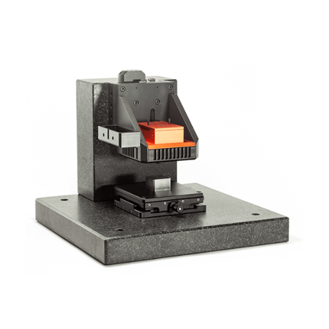
- Ideal for custom integration
- Automate serial measurements
- Copes with large, heavy, or curved samples
The surface morphology is an important property for many high-tech surfaces with features that can go down to a few nanometers and surface roughness below the nanometer. With AFM such features can be readily analyzed under ambient conditions. Most AFMs are limited in the type and size of samples they can handle. The NaniteAFM by Nanosurf is the market leading solution for AFM integration with least restriction to the sample dimensions.
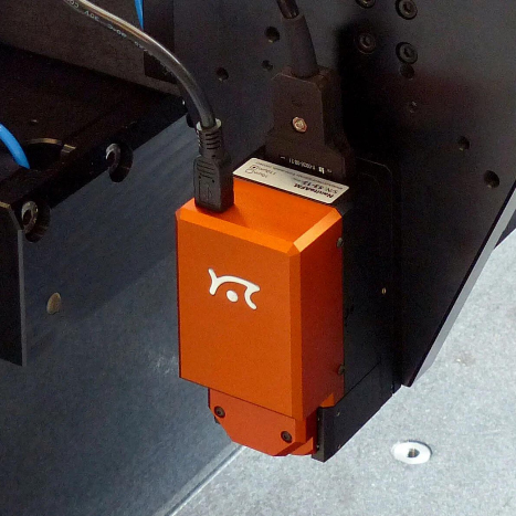
The NaniteAFM has a tip-scanner, two inspection video cameras and an on-board approach motor in an exceptionally small footprint. It contains everything needed to operate independently, paving the way for easy integration: All you need is 300 cm3 in space and a stable docking site to mount the AFM.
| NaniteAFM scan head specifications | 110 µm | 70 µm | 25 µm |
|---|---|---|---|
| Maximum scan range (XY)(1) | 110µm | 70 µm | 25µm |
| Maximum Z-range(1) | 22µm | 14 µm | 5 µm |
| XY-linearity mean error | < 0.6% | < 1.2% | < 0.7% |
| Z-measurement noise level (RMS, static mode) | typ. 350 pm (max. 500 pm) | typ. 350 pm (max. 500 pm) | typ. 80 pm (max. 150 pm) |
| Z-measurement noise level (RMS, dynamic mode) | typ. 90 pm (max. 150 pm) | typ.90 pm (max. 150 pm) | typ. 30 pm (max. 50 pm) |
| Mounting | Removable scan head (86 × 45 × 61 mm) with 3-point quick-lock mounting plate, mountable to Nanosurf or custom stages | ||
| Alignment of cantilever | Automatic self-alignment for cantilevers with alignment grooves | ||
| Automatic approach range | 4.5 mm (1.5 mm below focal plane of internal optics) | ||
| Sample observation | Dual USB video camera system (simultaneous top and side view): 5 MP, 1.4 mm x 1 mm, color top view and 5 MP, 3.1 mm x 3.5 mm, color side view of sample and cantilever |
||
| Sample illumination | White LEDs (brightness 0–100%); Axial illumination for top view | ||
| (1) Manufacturing tolerances are ±10% for the 110-μm scan head and ±15 % for the 70- and 25-μm scan heads (2) Maximum scan range at 45° scan rotation |
|||
| C3000i controller — Core hardware specifications | |
|---|---|
| X/Y/Z-axis scan and position controller | 3× 24-bit DAC (200 kHz) |
| X/Y/Z-axis position measurement | 1× 24-bit ADC (200 kHz) |
| Excitation & modulation outputs | 2× 16-bit DAC (20 MHz) |
| Analog signal input bandwidth | 0–5 MHz |
| Main input signal capturing | 2× 16-bit ADC (20 MHz) 2× 24-bit ADC (200 kHz) |
| Additional user signal outputs | 1× 24-bit DAC (200 kHz) |
| Digital synchronization | 2× digital out, 2× digital in, 2× I2C Bus |
| FPGA module and embedded processor | ALTERA FPGA, 32-bit NIOS-CPU, 80 MHz, 256 MB RAM, multitasking OS |
| Communication | USB 2.0 Hi-Speed to PC and scan head interface |
| System clock | Internal quartz (10 MHz) or external clock |
| Power | 90–240 V AC, 70 W, 50/60Hz |
| Cantilever requirements | |
|---|---|
| Width | min. 28 μm |
| Length | min. 225 μm or XY corrected |
| Reflective coating | Required on complete cantilever |
| Liquid measurements | Not possible |
| Alignment grooves | Required |
| Resonance frequency dynamic mode | 15 kHz to 350 kHz |
| Cantilever shape | Single rectangular cantilevers only |
| Chip thickness | 300 μm |