x
I
n
k
a
r
p
LensAFM
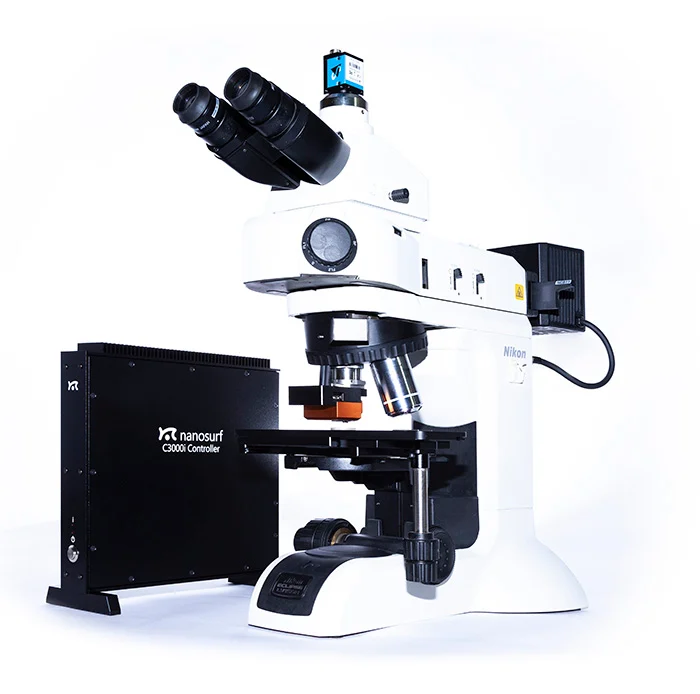

LensAFM Integration
Distributor & Service Provider In India
Inkarp Instruments, a trusted Nanosurf partner, offers LensAFM Integration in India, seamlessly combining Atomic Force Microscopy (AFM) with optical microscopy.
Extend the resolution of your optical microscope
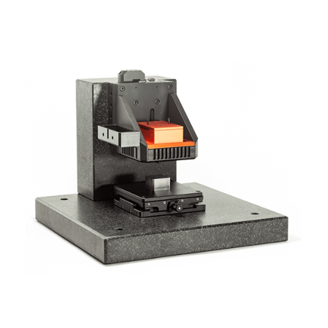
- Mountable on virtually any optical microscope or 3D optical profilometer
- Extend your resolution capabilities by a factor of up to 100
- Combine optical and AFM techniques
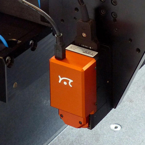
The Nanosurf LensAFM is an atomic force microscope that continues where optical microscopes and profilometers reach their resolution limits. It is mounted like a normal objective lens, thus extending the resolution and measuring capabilities of these instruments. The LensAFM not only provides 3D surface topography information, but can be used to analyze various physical properties of a measurement sample as well.
| LensAFM scan head specifications | 110-µm scan head | 70-µm scan head |
|---|---|---|
| Maximum scan range (XY)(1,2) | 110 µm | 70 µm |
| Maximum Z-range(1) | 22 µm | 14 µm |
| XY-linearity mean error | < 0.6% | < 1.2% |
| Z-measurement noise level (RMS, static mode)(3) | typ. 350 pm (max. 500 pm) | |
| Z-measurement noise level (RMS, dynamic mode)(3) | typ. 90 pm (max. 150 pm) |
|
| Automatic sample approach | Built-in motorized parallel approach with 4.5 mm travel | |
| Cantilever alignment | Automatic self-adjustment through alignment chip technology | |
| Sample observation(4) | Built-in 8× objective lens with 45 or 60 mm parfocal distance | |
| AFM measurement repositioning precision | ±10 µm (including cantilever exchange, scan head remounting and approach) | |
|
(1) Manufacturing tolerances are ±10% for 110-µm scan heads and ±15% for 70-µm scan heads (2) Maximum scan range at 45° rotation of the AFM scan direction (3) Measured using the C3000i controller, with active vibration isolation on a stable desk, and in a low-noise laboratory environment (no air conditioning) (4) Adapters with a correct parfocal distance are available for the different optical microscope types |
||
| C3000i controller — Core hardware specifications | |
|---|---|
| X/Y/Z-axis scan and position controller | 3× 24-bit DAC (200 kHz) |
| X/Y/Z-axis position measurement | 1× 24-bit ADC (200 kHz) |
| Excitation & modulation outputs | 2× 16-bit DAC (20 MHz) |
| Analog signal input bandwidth | 0–5 MHz |
| Main input signal capturing | 2× 16-bit ADC (20 MHz) 2× 24-bit ADC (200 kHz) |
| Additional user signal outputs | 1× 24-bit DAC (200 kHz) |
| Digital synchronization | Sync Out 1/2: digital outputs, signal range 0/5V TTL pulses |
| FPGA module and embedded processor | ALTERA FPGA, 32-bit NIOS-CPU, 80 MHz, 256 MB RAM, multitasking OS |
| Communication | USB 2.0 Hi-Speed to PC and scan head interface |
| System clock | Internal quartz (10 MHz) or external clock |
| Power | 90–240 V AC, 70 W, 50/60Hz |
| Cantilever requirements | |
|---|---|
| Width | min. 28 μm |
| Length | min. 225 μm or XY corrected |
| Reflective coating | Required on complete cantilever |
| Liquid measurements | Not possible |
| Alignment grooves | Required |
| Resonance frequency dynamic mode | 15 kHz to 350 kHz |
| Cantilever shape | Single rectangular cantilevers only |
| Chip thickness | 300 μm |